![]() 5.9-5.12 Daylighting
#
5.9-5.12 Daylighting
#
Introduction#
This page focuses on sections 5.9 through 5.12 of the CIE 171:2006 standard, evaluating Cyclops across four categories of daylight test cases: roof openings and wall openings, each with and without glazing. Every test configuration is simulated under all 16 CIE standard general sky types, producing a comprehensive validation of Cyclops's sky luminance model and daylight factor calculation.
Known Errata#
The following errata are relevant to the test cases covered in this report and have been taken into account when preparing these benchmarks:
-
Test Case 5.9 - Transposed Sky Type 3 values: The entries for CIE General Sky Type 3 in Table B1 (Section 5.9.3) are transposed. The corrected values from the errata have been used as the reference for the Cyclops validation.
-
Test Cases 5.10 & 5.12 - Unstated glass transmittance: CIE 171:2006 does not explicitly state the average transmittance of the 6 mm clear glass used in the glazed opening test cases. The errata derives a normal-incidence transmittance of 0.878 using the Mitalas and Arseneault (1968) equation for glass transmittance. This value has been adopted for the Cyclops benchmarks.
-
Test Case 5.11 - Uniform ground illuminance assumption: The errata notes that this test case assumes uniform external ground illuminance without accounting for shadowing of the ground by the building itself. Cyclops benchmarks are therefore run using the same assumption with uniform external ground illuminance.
Method#
Daylight Factor Components#
The test cases in sections 5.9–5.12 are structured around the daylight factor (DF), which quantifies the ratio of indoor illuminance at a point to the unobstructed outdoor horizontal illuminance. The daylight factor at a point P is decomposed into three additive components:
where:
-
SC (Sky Component) — the direct illuminance received at the point through the aperture from the sky.
-
ERC (External Reflected Component) — the illuminance contributed by light reflected from external surfaces entering through the aperture.
-
IRC (Internal Reflected Component) — the illuminance contributed by inter-reflections off interior room surfaces.
A key design choice in these test cases is that all interior surfaces have 0% reflectance, which eliminates the IRC entirely. This isolates the direct sky and ground contributions so that deviations in the results can be attributed specifically to the sky luminance model and aperture geometry handling, rather than to inter-reflection calculations.
For roof opening tests (5.9, 5.10), only the sky component contributes to the floor measurement points, since the floor sensors cannot see the ground through a horizontal opening above them.
For wall opening tests (5.11, 5.12), both the sky component and the external reflected component contribute. Floor sensors near the opening see the sky through the upper portion of the aperture and the ground through the lower portion. The external ground is assumed to be a uniform Lambertian reflector with a reflectance of 30%, and its luminance is derived from the external horizontal illuminance. Direct sun illuminance is excluded from all test cases.
Analytical Reference#
The CIE 171:2006 reference values are derived analytically rather than from physical measurements, eliminating measurement uncertainty from the comparison.
For CIE sky types 5 (uniform) and 16 (overcast), closed-form solutions exist. Under a uniform sky, the sky component equals the geometric configuration factor between the sensor point and the visible sky through the opening. Under a CIE overcast sky, the sky component for horizontal openings is given by the Tregenza (1993) formula that accounts for the non-uniform luminance distribution. A corresponding Tregenza formula exists for vertical (facade) openings.
For all other CIE sky types, the reference values were computed using Skylux, a purpose-built program that subdivides the aperture into thousands of sub-surfaces and integrates the luminance of the sky zone visible through each sub-surface from each measurement point. Skylux was validated against the closed-form solutions for sky types 5 and 16, with agreement to within 0.1%.
For the glazed test cases (5.10, 5.12), the sky component is further modulated by the directional transmittance of 6 mm clear glass, described by the Mitalas and Arseneault polynomial. Skylux applies this transmittance to each sub-surface based on the incidence angle between the sub-surface centre and the visible sky zone.
The reference values are published to two decimal places in the appendix tables of CIE 171:2006.
Test Configurations#
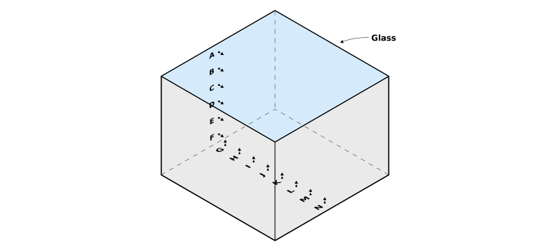
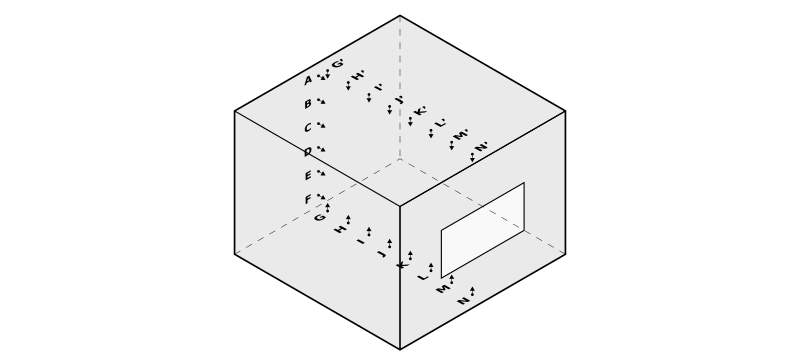
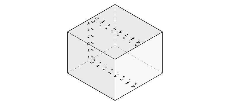
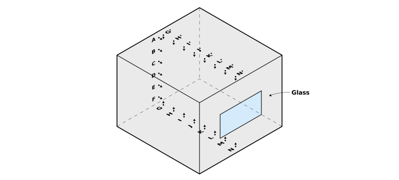
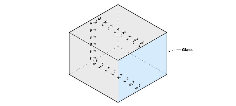
All test cases use a rectangular room of 4 m x 4 m x 3 m with a single opening. Wall thickness is not considered (zero thickness) for any test case. Four categories of configurations are tested, each with a small and large opening variant:
| Section | Opening Type | Opening Position | Opening Size | Glazing |
|---|---|---|---|---|
| 5.9 | Roof | Centre of ceiling | 1x1 m / 4x4 m | None |
| 5.10 | Roof | Centre of ceiling | 1x1 m / 4x4 m | 6 mm Clear |
| 5.11 | Wall | South facade | 2x1 m / 4x3 m | None |
| 5.12 | Wall | South facade | 2x1 m / 4x3 m | 6 mm Clear |
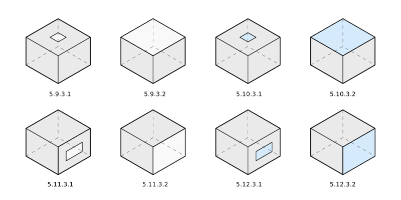
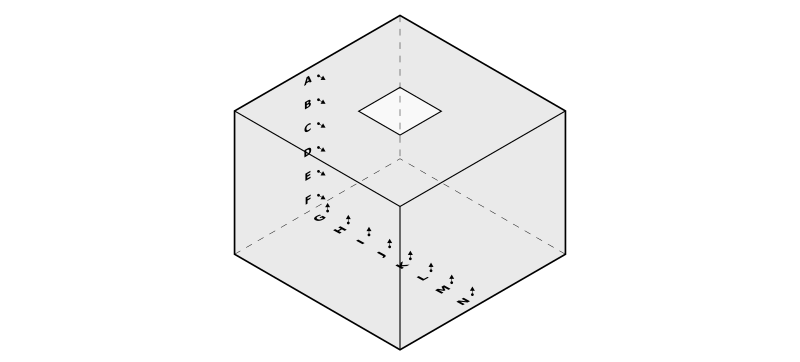
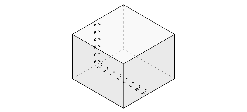
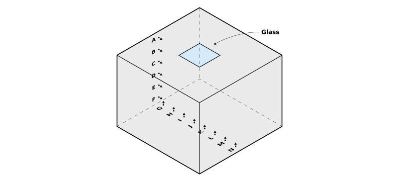
For each configuration, the daylight factor is measured at sensor points arranged in up to three groups. Points A–F are wall points spaced 0.5 m apart along the vertical room centerline on the north wall, starting 0.25 m from the floor. Points G–N are floor points spaced 0.5 m apart along the south-north centerline, starting 0.25 m from the north wall. For the roof opening tests (5.9, 5.10), these 14 points are sufficient since only the sky component is measured.
For the wall opening tests (5.11, 5.12), an additional set of 8 ceiling points G'–N' is included at the same horizontal positions as G–N but on the ceiling surface facing downward. The ceiling points can only see the external ground through the wall opening and therefore receive only the external reflected component (ERC). This brings the total to 22 sensor points for each wall opening configuration.
Sky Conditions#
Each configuration is tested under all 16 CIE standard general sky types (CIE S 011/E:2003), ranging from fully overcast (S01) through partly cloudy conditions (S06–S10) to clear sky (S12–S15), plus the CIE Traditional Overcast Sky (S16). This covers the full spectrum of sky luminance distributions.
For all test cases the sun position is fixed at south azimuth and 60° elevation. The direct sun illuminance component is excluded — only the diffuse sky luminance distribution is used.
Cyclops Simulation Setup#
This section describes how each test case was configured and executed in Cyclops. The workflow follows five steps: scene geometry, materials, analysis points, shading masks, sky instances, and daylight factor calculation.
Scene Geometry and Materials#
The room geometry for each test case is modelled as a triangulated mesh representing the walls, floor, and ceiling of the 4 m x 4 m x 3 m room, with the appropriate opening left in the ceiling or south wall depending on the test case. For the glazed test cases (5.10, 5.12), a single-surface mesh is placed across the opening to represent the glass pane.
Two materials are used. The room surfaces are assigned a plastic material with a black base colour, zero specularity and zero roughness, which produces a perfectly absorbing Lambertian surface matching the 0% reflectance specified by the standard. For the glazed configurations, the opening surface is assigned a glass material with a transparency of 0.878 corresponding to the normal-incidence transmittance of 6 mm clear glass derived from the Mitalas and Arseneault equation.
Analysis Points#
An analysis point is created at each sensor position. For the roof opening tests this is 14 points (A–F and G–N); for the wall opening tests this is 22 points (A–F, G–N, and G'–N'). Each analysis point has a direction vector perpendicular to its base surface — pointing inward for the wall points (A–F), pointing upward for the floor points (G–N), and pointing downward for the ceiling points (G'–N'). The positions are offset 0.1 mm from the room surfaces to prevent self-intersection with the room geometry during ray tracing.
Shading Masks#
A shading mask is computed for each analysis point. The shading mask maps the relationship between the analysis point and each cell of the sky hemisphere, taking the room geometry and materials into account. For each hemisphere cell, Monte Carlo rays are traced from the analysis point through the scene to determine a shading factor — a multiplier representing how much radiative energy from that sky cell reaches the point. Rays that hit the black room surfaces are absorbed and terminated. Rays that pass through the glass material (in glazed test cases) are attenuated by the glass transmittance and continue. Rays that escape through the opening reach the sky unobstructed.
The hemisphere is configured with 1,000 cells using the equal area aspect subdivision, which distributes cells evenly across the dome to avoid biasing any region of the sky. The sampling settings are set to 1,000 samples — meaning 1,000,000 (1,000²) rays per analysis point — to ensure thorough convergence of the Monte Carlo estimator. The max depth is set to 1, permitting a single bounce so that rays can pass through the glass surface in the glazed test cases.
Sky Instances#
A sky instance is created for each of the 16 CIE standard general sky types using the From CIE Sky Type constructor. Each sky instance is configured with:
-
A sun rig providing a single sun direction at 60° elevation due south.
-
A ground reflectance of 0.3, matching the 30% external ground reflectance specified by the standard.
-
Luminance components set to diffuse only, excluding the direct sun illuminance as required by the test cases.
-
The CIE Standard Sky Model as the luminance distribution model, which uses the updated formulation adopted by ISO/CIE for computing the CIE Standard General Sky luminance distributions.
The hemisphere used for the sky instances matches the 1,000-cell equal area aspect hemisphere used for the shading masks.
Daylight Factor Calculation#
The daylight factor is calculated for each analysis point by multiplying its shading mask with the sky instance. This produces the ratio of illuminance at the analysis point to the illuminance on an unobstructed horizontal surface under the same sky, expressed as a percentage. The calculation is repeated for each of the 16 sky instances, yielding 224 daylight factor values (14 points x 16 skies) per roof opening configuration and 352 values (22 points x 16 skies) per wall opening configuration — a total of 2,304 values across all eight configurations.
How to Read the Results#
Each test case below includes two plots:
-
Line plot (per sky type): A tabbed line plot that can be switched between all 16 CIE standard sky types. Each view overlays the Cyclops result (solid blue) and the benchmark reference (solid red) across all sensor points, with an information panel in the top-right corner showing the mean absolute deviation, maximum deviation, and minimum deviation for the selected sky type. This provides a visual comparison of the spatial profile for every sky condition.
-
Deviation heatmap: Shows the deviation from the benchmark reference value for each combination of sky type (rows) and sensor point (columns). White indicates strong agreement; blue indicates under-prediction and red indicates over-prediction. Hover over any cell to see the exact Cyclops value, benchmark reference value, and deviation. Because the CIE reference values are published at two decimal places, a rounding tolerance of half a unit in the last place (0.005 DF) is subtracted from each absolute difference before computing the deviation, so that discrepancies explainable by rounding alone are not overstated.
Results#
The following box-and-whisker plot provides an overview of the percentage deviation from the benchmark across all eight test configurations. Each box shows the median, interquartile range (IQR), and whiskers extending to 1.5× IQR, with outliers plotted individually. This gives a quick visual comparison of accuracy and spread across the full test suite before examining each case in detail.
5.9 — Sky Component for a Roof Unglazed Opening#
This test case verifies the calculation of the sky component through an unglazed horizontal (roof) opening under all 16 CIE general sky types. Because the opening is in the roof and all interior surfaces are black, only the sky component (SC) contributes to the measured daylight factor.
5.9.3.1 — 1x1m Roof Opening, No glass#
5.9.3.2 — 4x4m Roof Opening, No glass#
5.10 — Sky Component under a Roof Glazed Opening#
This test case extends 5.9 by adding a 6 mm clear glass pane over the roof opening. The objective is to verify the simulation's ability to model the influence of directional glass transmittance on the sky component under all 16 CIE sky types.
The presence of glazing modulates the sky component because the transmittance of the glass varies with the angle of incidence. Light arriving at steep angles (near the edge of the opening's field of view from a sensor point) is attenuated more than light arriving at near-normal incidence. The directional transmittance is described by the Mitalas and Arseneault polynomial for 6 mm clear glass, which yields a normal-incidence transmittance of 0.878.
5.10.3.1 — 1x1m Roof Opening, 6mm glass#
5.10.3.2 — 4x4m Roof Opening, 6mm glass#
5.11 — SC and ERC for a Facade Unglazed Opening#
This test case introduces a vertical (facade) opening in the south wall, which fundamentally changes the light distribution compared to a roof opening. With a wall opening, the external ground plane is partially visible through the aperture and contributes reflected light to the room interior — particularly to the ceiling and upper wall surfaces. This means the measured quantity is now the sky component plus the external reflected component (SC + ERC), rather than SC alone.
The external ground is modelled as a uniform Lambertian reflector with 30% reflectance. Its luminance is calculated from the external horizontal illuminance. The ERC at a measurement point is given by the configuration factor between the point and the ground-visible zone of the opening, multiplied by the ground reflectance.
5.11.3.1 — 2x1m Wall Opening, No glass#
5.11.3.2 — 4x3m Wall Opening, No glass#
5.12 — SC and ERC for a Facade Glazed Opening#
This test case combines the facade geometry of 5.11 with the glazed aperture of 5.10. The objective is to verify the daylight factor calculation under all 16 CIE sky types when both the directional glass transmittance and the external ground reflection are in play simultaneously. The same 6 mm clear glass and 30% ground reflectance are used. The analytical reference values are computed with Skylux, validated against the closed-form solution for the CIE overcast sky.
5.12.3.1 — 2x1m Wall Opening, Glass#
5.12.3.2 — 4x3m Wall Opening, Glass#
Conclusion#
This benchmark validates Cyclops against the CIE 171:2006 analytical reference for test cases 5.9-5.12, across 8 configurations, 16 sky types, and 2,304 individual data points. The line plots demonstrate strong agreement between Cyclops and the benchmark across all configurations, and the deviation heatmaps confirm that deviations from the benchmark are generally small and evenly distributed.
The results are consistent across both roof and wall opening geometries, with and without glazing, and across the full range of CIE standard sky types from overcast to clear. This demonstrates that Cyclops's sky luminance model, daylight factor calculation, and directional glass transmittance handling are well aligned with the internationally recognised CIE standard.
Warning
CIE 171:2006 5.9-5.12 test cases use simple rectangular rooms with uniform surface properties and zero-thickness walls. While the results validate the core simulation engine, more complex real-world geometries may introduce additional factors not covered by this standard.